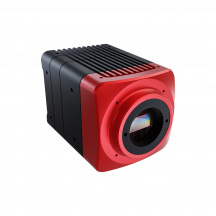
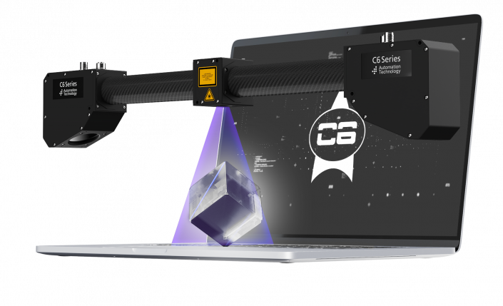
3D camera for maximum flexibility
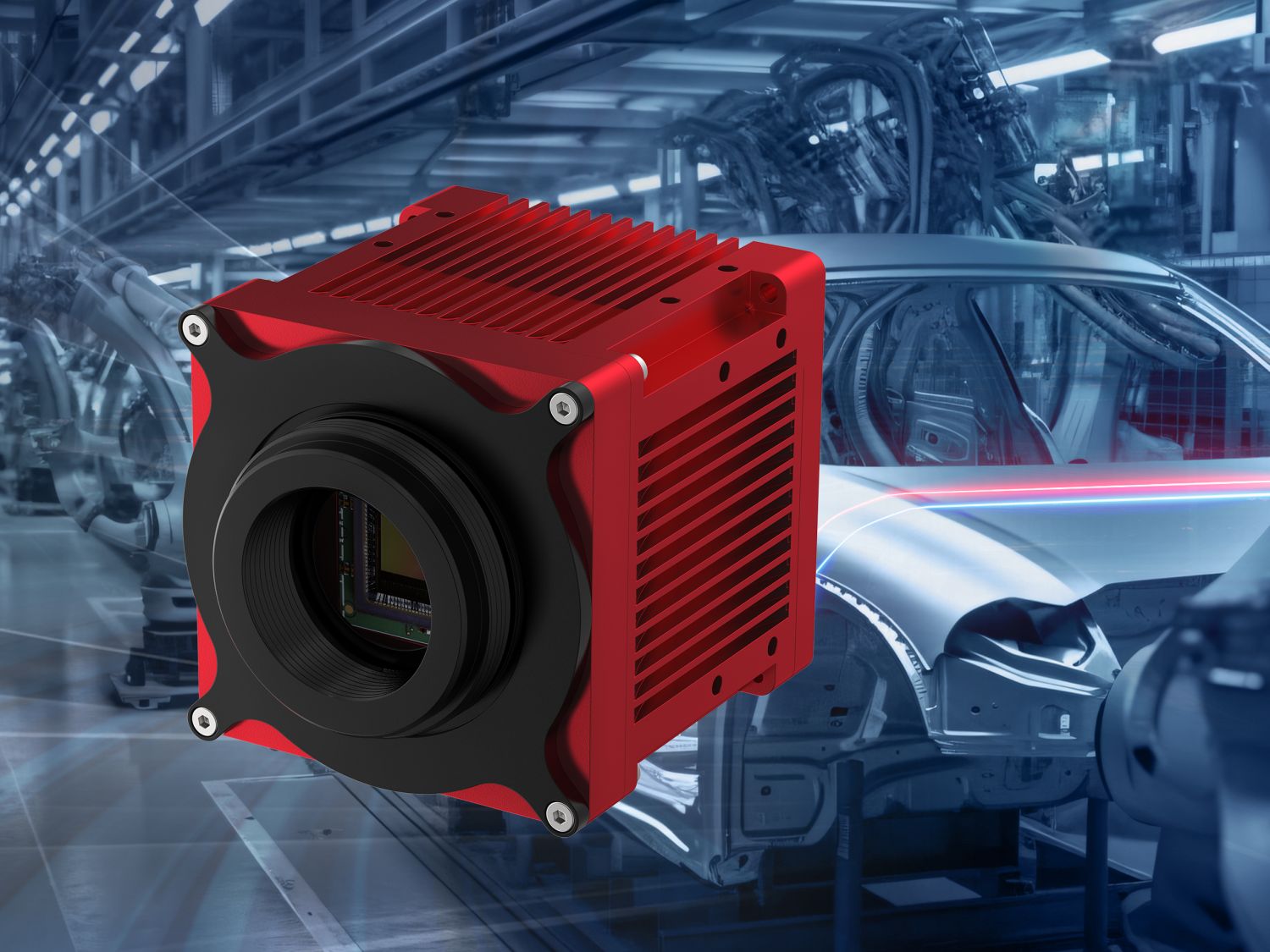
Designed for users who want to configure the 3D set-up themselves and choose components such as lasers or lenses.
-
Compatible with custom components
-
Ideal for custom application design
-
Optimal for complex multi-sensor applications
-
Perfect 3D imaging through integrated Scheimpflug arrangement
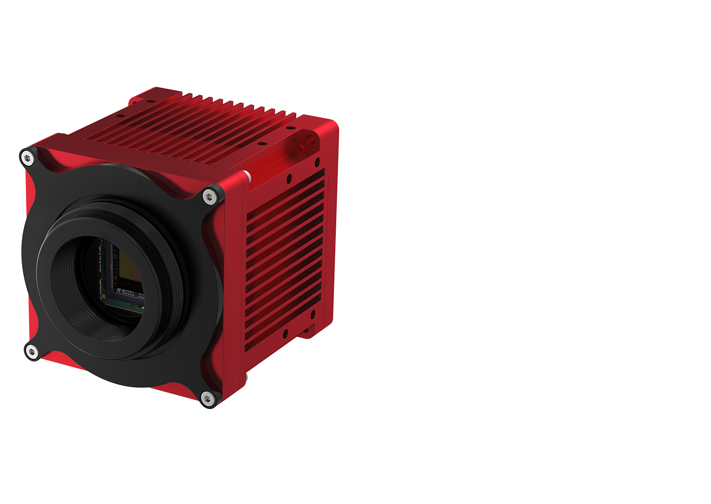
Our 3D cameras combine extreme speed with high-precision resolution
The CA camera series delivers fast, precise 3D image capture for demanding industrial applications. With resolutions up to 3072 pixels and Ethernet interfaces from 1G to ultra-fast 5G, both models offer outstanding performance and easy system integration.
The C6-CA Series provides high-resolution 3D imaging, while the C7-CA Series adds maximum speed and direct laser connectivity for advanced multi-sensor setups.
C6 3070
The best 3D sensor chip

Warp Speed
Galactical speed
On-Sensor Processing
Focus on relevant data transmission
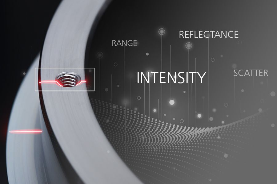
MultiPart
Simultaneous output of multiple data sets

MultiPeak
Disturbance-free scans of reflective materials
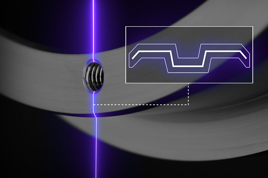
REGION SEARCH UND REGION TRACKING
Secure detection and classification of the laser line

INTELLIGENT ALGORITHMS
Reliable definition of the laser line profile
Technical Specifications
-
Camera data
High dynamic range features: Multiple Slope Mode 3D algorithms: MAX, TRSH, COG, FIR PEAK 3D scan features: Automatic Region Tracking, Automatic Region Search, Multiple Regions, AutoStart Connections 17 pin, M12 Power I/O
8pin, M12 EthernetData interface Gigabit Ethernet (1Gbit/s) Standards GigE Vision with GenICam Temperature Operation 0°C to +40°C
Storage -20°C to +80°CProtection class IP67 Sensor specifications
Power consumption max. 15 W Power supply sensor 10-24 V DC (max. 27 V DC) I/O specifications
Digital input: 2 electrical isolated inputs, +5V to +24V DC Digital output: 2 electrical isolated outputs, +5 to +24V DC (max. 100 mA) Analogue output: 0V to +5V DC Encoder/Resolver input: A+, A-, B+, B-, Z+, Z- High-Speed Triple RS-422 Receiver Max. input voltage +5V DC (TTL level) Lens interface
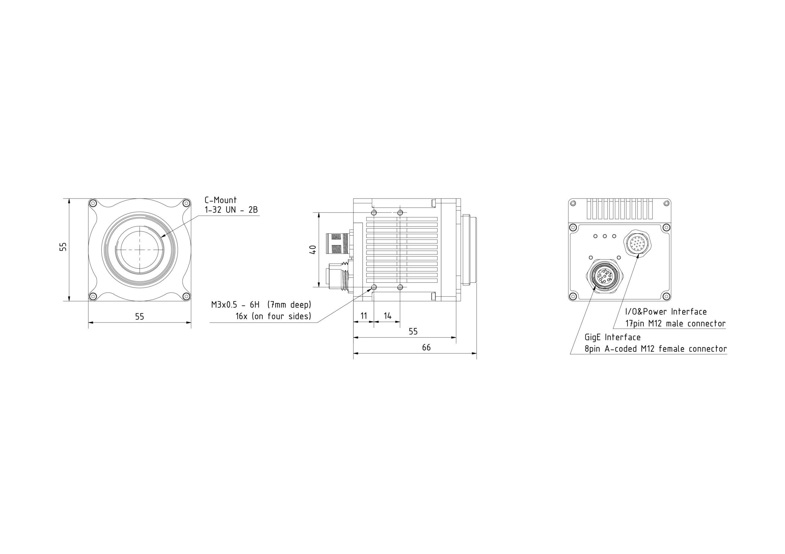
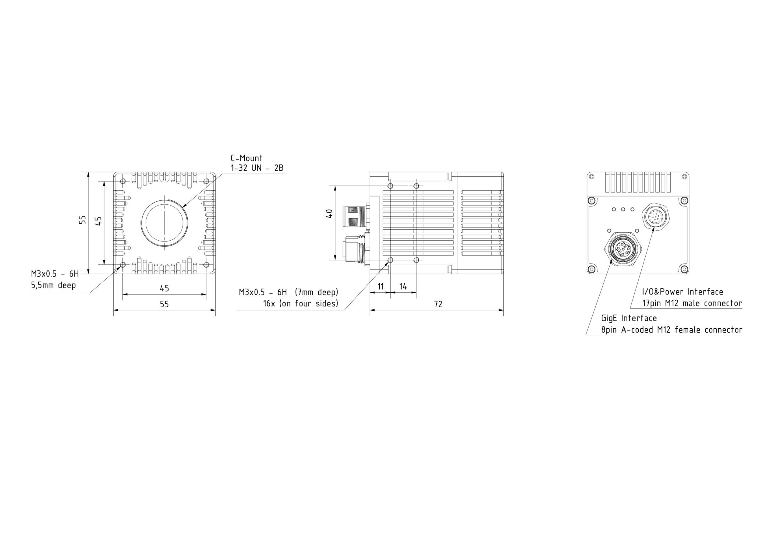
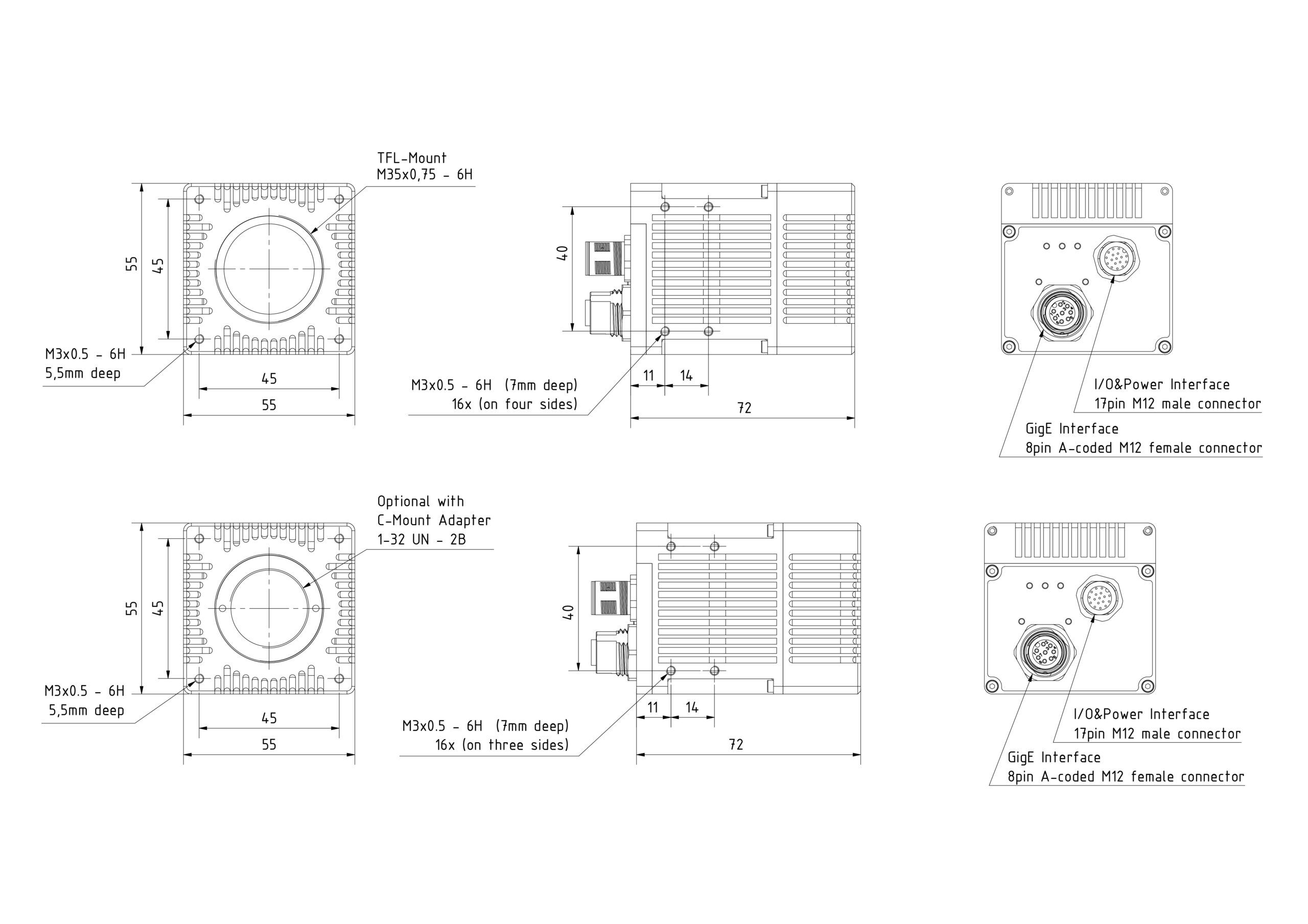
Cameras without scheimpflug angle M42x1 (Adapter for C-Mount and F-Mount available) Cameras with integrated scheimpflug angle C-Mount / TFL-Mount -
Models in comparison
C6-1280 C6-2040 C6-3070 C6-3070W C6-4090 Sensor type CMOS Shutter type Global shutter Resolution (H xV) 1280 x 1024 Pixel 2048 x 1088 Pixel 3072 x 1020 Pixel 3072 x 1020 Pixel 4096 x 3072 Pixel Pixel size 6.6 µm x 6.6 µm 5.5 µm x 5.5 µm 6.6 µm x 6.6 µm 6.6 µm x 6.6 µm 5.5 µm x 5.5 µm Sensor size 8,448 mm x 6,758 mm 11,264 mm x 5,984 mm 20,275 mm x 6,732 mm 20,275 mm x 6,732 mm 22,528 mm x 16,896 mm Image circle 10,82 mm 12,75 mm 21,37 mm 21,37 mm 28,16 mm Sensor format 2/3″ 2/3″ 1,5″ 1,5″ 1,75″ Power consumption max. 15 W ADC resolution 12 bit 10 bit 10 bit 10 bit 10 bit Extended dynamic range Up to 90 dB with activated Multi Slope Mode Scan 3D extraction process MAX, TRSH, COG, FIR PEAK High dynamic range imaging Multi Slope Mode 3D features Multipeak, Multipart, Region Tracking/Search, Autostart Typical Profile Speed Depending on Number of Sensor Rows (Hz)*
Rows 1280 2040 4090 688 Profile Width 1280 Profile Width 4 172744 121130 43478 24875 8 128388 84034 29412 20352 16 84826 52113 18182 14925 32 50533 29615 10204 9733 64 27942 15893 5435 5740 128 14752 8249 2809 3153 256 7588 4204 1429 1658 512 3849 2123 720 851 1024 1939 1067 362 431 Full Frame 1939 1067 341 145 *Internal values. The actual usable profile speed may be limited by the 1 Gbit/s interface.
Typical Profile Speed Depending on Number of Sensor Rows (Hz)*
Rows 3070 3070W Warp1 3070W Warp2 3070W Warp3 3070W Warp4 6 66489 66225 81833 88967 94517 12 47846 66225 81833 88967 94517 24 30656 56433 81833 88967 94517 48 17838 34199 61425 88967 94517 96 9714 19127 35971 64267 72150 192 5083 10166 19669 36927 42052 384 2602 5248 10317 19952 22925 768 1317 2667 5288 10395 12004 Full Frame 994 2016 4007 7908 9145 *Internal values. The actual usable profile speed may be limited by the 1 Gbit/s interface.
-
FAQ
The costs naturally depend on the application and level of customization, but our sensors start at a price of $6,500.

